A customer sent back 14,000 vials last March because their autosampler started throwing “vial not found” errors on roughly 3% of a 96-position tray. The vials were 12 x 32 mm, 9 mm screw thread, purchased against a drawing that said “12.0 x 32.0 mm.” That drawing had no tolerance block. The actual lot measured 31.62 mm on the short side of the crimp skirt, 0.38 mm under nominal, and the gripper on their autosampler vial handler was closing on air. The dimensional tolerance capability of the molding process was never specified, so nobody could tell whether the lot was bad or the drawing was. This article is about how to specify that capability, how to measure it, and which dimensions you cannot buy your way out of.
Three processes make the clear or amber body you put in the tray: injection molding, injection blow molding, and extrusion blow molding. They do not hold the same tolerances, and no supplier can quote you a single number across all three. When a catalog says “±0.1 mm” with no process attached, that number came from the best cell in the plant and applies to one dimension on one machine.
Here is what I have measured across production lots, not what the datasheets claim. These are capability figures (Cpk around 1.33, roughly 4 sigma) on a well-run line, not the extreme values from a single good shift.
| Dimension | Injection molded | Injection blow molded | Extrusion blow molded |
|---|---|---|---|
| Body OD (nominal 12.00 mm) | ±0.08 mm | ±0.15 mm | ±0.30 mm |
| Overall height (nominal 32.00 mm) | ±0.12 mm | ±0.20 mm | ±0.40 mm |
| Neck ID (9 mm finish) | ±0.10 mm | ±0.15 mm | ±0.25 mm |
| Wall thickness (nominal 1.0 mm) | ±0.05 mm | ±0.10 mm | ±0.20 mm |
| Bottom concentricity (TIR) | 0.10 mm | 0.20 mm | 0.40 mm |
The pattern is not subtle. Injection molding holds the tightest band because the cavity defines every surface at once and the shrink is uniform across a 1 mm wall. Blow molding stretches a parison against a mold, so wall thickness varies with the stretch ratio, and the bottom, where the parison folds, is the worst place in the part. If your method needs the vial to sit within 0.15 mm of a fixed Z height in the tray, injection blow molding is marginal and extrusion blow molding will not get you there.
Glass is a separate conversation. A Type I borosilicate vial from a good draw holds ±0.10 mm on OD and ±0.25 mm on height routinely, but the crimp finish on glass has its own tolerance stack, and the neck ID drifts more than the body because the forming happens hot and fast. If you are comparing glass and plastic on dimensional tolerance capability alone, they land in similar territory on the body and glass wins on the neck.
How to measure capability instead of buying a certificate that says “in spec”
A certificate of analysis that says “conforms” tells you the sample passed. It does not tell you the process can keep passing. Those are different questions, and only one of them predicts what happens on your autosampler six months from now.
Capability is a ratio, not a range
Ask your supplier for Cpk on each critical dimension, computed from at least 30 consecutive parts off one cavity over at least three production runs. Cpk is the smaller of (USL minus mean) and (mean minus LSL), divided by 3 sigma. A Cpk of 1.33 means the process mean sits 4 sigma from the nearest limit. A Cpk of 1.0 means 3 sigma, which sounds fine until you remember that a normal process throws about 2,700 parts per million outside 3 sigma. On a 100,000-piece order that is 270 vials your autosampler has to deal with.
I want Cpk at or above 1.33 on height, OD, and neck ID, and 1.67 on anything the autosampler gripper touches. The gripper is unforgiving. A 0.2 mm shift in the crimp skirt diameter changes whether the jaws seat or slip, and the machine reports it as a positioning fault, not a vial fault.
Gauge R&R first, then capability
Capability numbers are worthless if the measurement system eats half the tolerance. Before you accept a Cpk value, ask what gauge they used and what the gauge R&R is. On a 12 mm OD with a ±0.08 mm tolerance, a caliper with 0.02 mm resolution and 0.03 mm repeatability will consume 30-40% of the tolerance band in measurement variation alone. That inflates sigma and deflates Cpk, or worse, hides a real drift. Optical comparators and air gauges are the right tools here. Hand calipers are for receiving inspection, not capability studies.
The three-run rule
One run is a snapshot. Capability has to survive a tool change, a resin lot change, and a shift change. Ask for capability data from three separate production runs at least two weeks apart, and check that the means are stable. If the mean on height walks 0.05 mm between runs, the process is drifting on mold temperature or cycle time, and the Cpk you were shown was measured on the good day.
The dimensions that fight back: height, concentricity, and the crimp skirt
Some dimensions are easy. Body OD on an injection molded vial is a cavity dimension, and the cavity does not move. The hard ones are where two features have to agree with each other, or where the plastic is still moving when the mold opens.
Overall height and the shrink problem
Height is set by the distance between the cavity bottom and the gate, and it moves with every degree of mold temperature. PP shrinks about 1.5-2.0% from mold to room temperature, and the shrink is not uniform along a 32 mm part because the bottom is thicker than the wall. A 2°C drift in the cooling water moves the mean height by roughly 0.03 mm. Over a 12-hour run that is enough to push a marginal process from Cpk 1.2 to Cpk 0.9. This is why height is the dimension that shows up in “vial not found” complaints: the handler references the bottom of the vial, and 0.3 mm of height error puts the needle guide in the wrong place.
Bottom concentricity and the needle
Total indicated runout on the bottom face is the dimension nobody specifies and everybody should. If the bottom is not concentric to the OD within about 0.10 mm, the vial sits slightly tilted in the tray, and a fixed-height needle guide either grazes the septum off-center or misses it. Off-center puncture is one of the quiet causes of coring, and it shows up as a septum plug in the needle, not as a dimensional failure. I have seen a lot with 0.25 mm TIR pass every dimensional check on the drawing and still coring at 4% because the drawing never called out concentricity.
The 9 mm crimp skirt
On a screw-thread vial the skirt is molded, and the thread pitch and major diameter matter for cap torque. On a crimp vial the aluminum seal does the work, but the glass or plastic finish underneath has to be round within about 0.08 mm or the crimp pulls unevenly and the seal leaks on one side. This is the dimension where glass and plastic diverge most, and where a cheap mold shows up first.
Two lots, two measurements, two different fixes
Case one: the drifting height. A contract lab running a 96-well tray on a Thermo autosampler started seeing 1.8% “vial not found” errors after switching to a new lot of injection molded vials. Receiving inspection passed the lot because every vial was within the ±0.30 mm height tolerance on the purchase order. We measured 60 vials with a height gauge and found the mean at 31.74 mm, with the whole distribution shifted low, not scattered. The fix was not tighter tolerance. The fix was a call to the molder, who had changed cooling water setpoint from 18°C to 22°C to speed cycle time. Mean came back to 31.95 mm on the next run. The lesson: a shifted mean with tight scatter is a process setpoint problem, and a tolerance change will not fix it. Ask for the mean and sigma separately, not just the pass rate.
Case two: the concentricity that wasn’t on the drawing. A pharma QC group had a 3.5% coring rate on a headspace method. The septa were the right spec, the crimper was calibrated, the torque was 1.2 N·m. We pulled 40 vials and measured bottom TIR on an optical comparator: mean 0.18 mm, max 0.31 mm. The vials were within height and OD tolerance, but the bottom face was not square to the axis, so the vial sat tilted and the needle entered at an angle. The fix was a drawing change adding 0.10 mm TIR on the bottom face, and the molder moved the gate location to fix the warp. Coring dropped to 0.2%. The HPLC vial was never “out of spec” because the spec did not exist.
Writing a tolerance block that a molder can actually hold
Most vial drawings I see have a title block, a material callout, and a single “12 x 32 mm” with no tolerance. That drawing cannot be manufactured to capability because it does not define what capability means. Here is the block I put on every vial drawing now, and it has cut incoming rejections by more than half across our contract customers.
- Body OD: 12.00 ±0.10 mm, Cpk ≥ 1.33, measured at mid-height, 90° apart, two readings per vial.
- Overall height: 32.00 ±0.20 mm, Cpk ≥ 1.33, measured from bottom face to top of finish.
- Bottom TIR: 0.10 mm max, referenced to body OD.
- Neck ID (9 mm finish): per GPI 9 mm thread spec, Cpk ≥ 1.33.
- Wall thickness: 1.0 ±0.10 mm, minimum 0.85 mm at any point.
- Concentricity of neck to body: 0.10 mm TIR.
- Resin: virgin PP or COC, no regrind above 15%, documented on the CoA.
- Capability data: three runs, 30 parts each, gauge R&R ≤ 10% of tolerance, submitted with first article.
Two notes on that block. The GPI 9 mm finish is the standard the cap and crimper are built to, so referencing it is faster than writing your own thread spec. And the regrind limit matters for dimensional tolerance capability more than people expect: regrind changes shrink, and a molder running 30% regrind will drift on height without touching a setpoint.
What the tolerance on the drawing does not cover
A dimensional spec controls the molded part. It does not control the assembled vial, and several failure modes live in the gap. Septum compression, cap torque, and the flatness of the seal face are assembly variables, and they interact with the molded dimensions in ways a single-part drawing cannot capture.
If you are running headspace, the headspace vial has an additional constraint: the crimp finish has to hold pressure at 120-150°C for the cycle, and thermal expansion of the plastic changes the effective OD by 0.1-0.2 mm at those temperatures. A vial that fits the tray cold can bind when hot. This is where the tolerance on the drawing and the tolerance in the oven diverge, and it is why headspace vials get their own capability study at temperature, not just at 20°C.
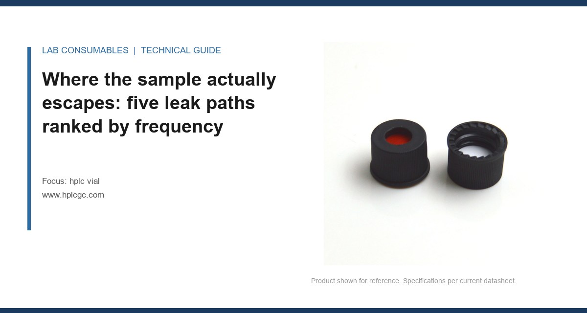
The other gap is the septa and caps. A vial with a perfect molded body and a cap with 0.3 mm of flash on the sealing lip will leak. Torque on a screw cap should land between 1.0 and 1.5 N·m for a 9 mm PP thread; below 0.8 N·m you get evaporation loss, above 1.8 N·m you deform the cap and crack the finish. The molded vial tolerance sets the thread engagement, but the torque is set by your capper, and no drawing controls that.
Receiving inspection that catches drift before the autosampler does
You cannot inspect capability into a lot. But you can catch a mean shift before it reaches the tray. This is the checklist I use on incoming lots, and it takes about 20 minutes per lot with the right tools.
- Sample 30 vials from at least three positions in the carton (top, middle, bottom).
- Measure height and OD on a height gauge with 0.01 mm resolution, record mean and sigma, compare to the last three lots.
- Check bottom TIR on 10 vials with an optical comparator or a dial indicator on a rotating fixture.
- Fit test: load 10 vials into an empty tray and run a dry cycle through the autosampler. Any “not found” error is a fail.
- Cap fit: torque 5 vials to 1.2 N·m and check for thread stripping or cap cracking.
- Trend chart: plot the lot mean against the previous 10 lots. A shift of more than 0.05 mm on height is a supplier conversation, not a reject.
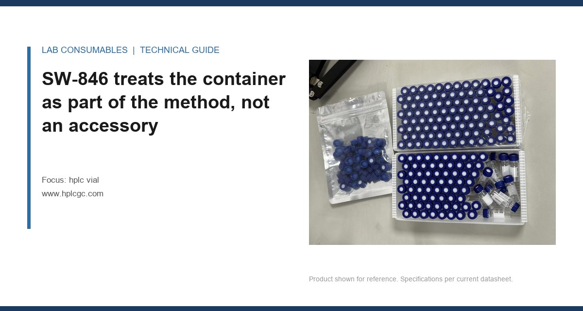
That last item is the one people skip. A lot that is in spec but 0.05 mm off the trend is the early warning. Catching it there is cheaper than catching it in a failed run, and it gives the molder time to correct a setpoint before the next lot ships. The EPA SW-846 methods treat the container as part of the method, and a trend chart is how you keep the container inside the method without revalidating.
The decision rule for tolerance capability
Specify capability, not just limits, and put the capability requirement on the drawing with the gauge and the sampling plan attached. If a supplier cannot give you Cpk on height, OD, neck ID, and bottom TIR from three runs with gauge R&R under 10%, they are selling you a pass rate, not a process, and your autosampler will eventually find the difference. The dimensions that matter most are the ones where two features have to agree (concentricity, neck-to-body alignment) and the ones that move with process temperature (height, wall thickness). For the rest, a ±0.10 mm band on the body and ±0.20 mm on height, held at Cpk 1.33, is enough for any 12 x 32 mm platform I have run, and it is what I write on the drawing before I place an order. For reference specs on the finish and the cap interface, the Agilent consumables catalog, the Thermo Fisher sample handling documentation, and the Restek technical library all publish the interface dimensions the instruments are built to, and those are the numbers your tolerance block should agree with.
References & further reading
Related resources from our lab consumables network:
- Hplc Vial at hplcgc.com
- Autosampler Vial at autosamplerhplc.com
- Vial at vials-filters.com
- Headspace Vial at headspacevialsupplier.com
External references and standards: